Path2D インスタンスとその API メソッドおよびプロパティにより、UI エフェクト(パスベースのアニメーションやグラフエディターなど)に役立つ 2D スプラインと 2D 曲線を実装できます。
2D パスの作成
Path2D を画面またはインエクスペリエンスオブジェクトに追加するには:
Explorer ウィンドウで、可視の ScreenGui または SurfaceGui の下に Path2D インスタンスを挿入します(直下の子である必要はありません)。

新しい Path2D を選択して、インビューポートツールウィジェットを表示します。デフォルトでは、Add Point ツールが選択されています。

完了したら、ウィジェットの 完了 ボタンをクリックするか、Enter を押します。


制御点を変更する
Explorer 階層で Path2D を選択すると、その個々の制御点とそのタンジェントを変更できます。
ポイントを移動したり
パス上の個々の制御点を移動するには、選択 ツール (V) を有効にし、マウスでクリック&ドラッグして新しい位置に移動します。


特定の位置決めには、制御点を選択し、プロパティ ウィンドウでそのポイントの SelectedControlPointData プロパティ (UDim2) に新しい位置を設定します。

点の位置は絶対的なものではなく、パスの親コンテナに対して相対的です。たとえば、ScreenGui 内のパスの左から 30%、上から 20% の制御点と、ScreenGui の右上隅にある Frame 内の同一のパスを比較してください。

ポイントを追加する
新しい制御点は、既存の 2 つのポイントの間や、いずれかの端点から Add Point ツール (P) を使用して追加できます。


ポイントを削除する
制御点を削除するには、それにホバーし、右クリックして、コンテキストポップアップメニューから Delete Point を選択します。

制御点タンジェント
制御点 タンジェント は、パス上の曲線を作成および調整することができます。

タンジェントを追加する
タンジェントを持たない制御点にタンジェントを追加するには:
ツーリングウィジェットで Add Tangent ツールを有効にします。


タンジェントを調整する
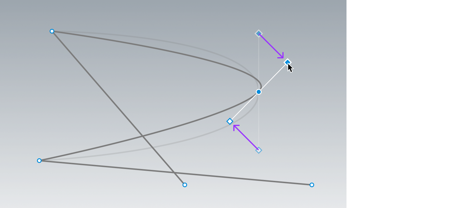
個々の制御点の既存のタンジェントを調整するには:
選択 ツール (V) を有効にします。

タンジェントマーカー(制御点ではなく)にホバーし、クリック&ドラッグして新しい位置に移動します。タンジェントがミラーリングされている場合、ペアとなるタンジェントポイントも一緒に動きます。
特定の UDim2 位置をタンジェントに手動で設定するには:
選択 ツール (V) を有効にし、制御点を選択します。 プロパティ ウィンドウで、SelectedControlPointData フィールドを展開して、LeftTangent および RightTangent プロパティを表示します。

LeftTangent と/または RightTangent の位置を設定します。この操作により、タンジェントのミラーリング動作が破壊されることに注意してください。

タンジェントを削除する
制御点から両方のタンジェントを削除するには、そのポイントにホバーし、右クリックして、コンテキストポップアップメニューから Clear Tangents を選択します。

一方のタンジェント(左または右)のみを削除するには、そのタンジェントのマーカーにホバーし、右クリックして Delete Tangent を選択します。

破壊とミラー
デフォルトでは、タンジェントは互いにミラーリングされます。調整するために一方のタンジェント マーカーをドラッグすると、ペアのタンジェントポイントも一緒に移動します。

タンジェントをそれぞれ独立して移動できるようにするために「壊す」には、関連する制御点にホバーし、右クリックしてコンテキストメニューから Break Tangents を選択します。一度壊すと、他に影響を与えずに各タンジェントマーカーを移動できます。

パスの視覚プロパティ
次のプロパティを使用して、Path2D の視覚的な外観をカスタマイズできます:
| プロパティ | 説明 |
|---|---|
| Color3 | パスラインの色を設定します。 |
| Thickness | パスラインの太さ(ピクセル単位)を設定します。 |
| Visible | 編集およびランタイムの両方でパスを表示するかどうかを設定します。 |
| ZIndex | 他の GUI に対するパスの表示順序を設定します。 |

Color3 = (125, 125, 125)

Color3 = (225, 0, 50)

パススクリプティング
スクリプティングは、いくつかのパス関連のワークフローに役立ちます。以下の例では、GetControlPoints() や GetPositionOnCurveArcLength() といったメソッドを使用します。これらはそれぞれ Path2DControlPoints のテーブルや、指定された t 値に沿ったスプラインの UDim2 位置を返します。
UI オブジェクトをパスに沿って配置
local parent = script.Parent
local path = parent:FindFirstChildWhichIsA("Path2D")
local function arrangeChildren()
local segmentCount = #path:GetControlPoints()
local objectsToArrange = {}
for _, child in parent:GetChildren() do
if child:IsA("GuiObject") then
table.insert(objectsToArrange, child)
end
end
for idx, child in objectsToArrange do
local t = idx / (#objectsToArrange + 1)
child.Position = path:GetPositionOnCurveArcLength(t)
end
end
-- パス全体に子UIオブジェクトを初期配置
arrangeChildren()
-- 子が追加/削除された時に配置を調整
parent.ChildAdded:Connect(arrangeChildren)
parent.ChildRemoved:Connect(arrangeChildren)
パスに沿って UI オブジェクトをアニメート
local Tweenservice = game:GetService("TweenService")
local parent = script.Parent
local path = parent:FindFirstChildWhichIsA("Path2D")
local objectToAnimate = parent:FindFirstChildWhichIsA("GuiObject")
local TWEEN_DURATION = 4
local TWEEN_EASING_STYLE = Enum.EasingStyle.Cubic
local TWEEN_EASING_DIRECTION = Enum.EasingDirection.InOut
local pathSampleValue = Instance.new("NumberValue")
local tweenInfo = TweenInfo.new(TWEEN_DURATION, TWEEN_EASING_STYLE, TWEEN_EASING_DIRECTION, 0, true, 2)
local tween = Tweenservice:Create(pathSampleValue, tweenInfo, {Value = 1})
local function onSampleValueChanged()
objectToAnimate.Position = path:GetPositionOnCurveArcLength(pathSampleValue.Value)
end
pathSampleValue.Changed:Connect(onSampleValueChanged)
tween:Play()