Spinning objects are objects that rotate on one or more axes within the 3D space. Using the built-in power of Roblox's simulation engine, you can make objects spin and interact with their environment in a way that emulates real-world physical behavior that's familiar and intuitive to players, such as gravity, aerodynamics, and friction.
Using the Spinning Objects .rbxl file as a reference, this tutorial explains how physical forces impact angular motion in Studio, and shows you various techniques to spin objects in your experiences with different spinning behavior, including guidance on:
- Using an AngularVelocity mover constraint to spin an entire assembly at a constant angular velocity.
- Using a HingeConstraint mechanical constraint to spin a part within an assembly at a constant angular velocity as the rest of the assembly remains stationary.
- Using the ApplyAngularImpulse method to spin an assembly with an initial impulse of angular force so that the assembly slowly decelerates over time.
Angular Motion and Physical Forces
Roblox Studio is a real-world simulation engine that emulates physical behavior in real time, so in order to predict the behavior of spinning objects in experiences, it's important to have a high-level understanding of how objects spin in real life with angular motion.
Angular motion, or rotational motion, is movement around a fixed point or axis. For example, when a propeller has angular motion, it spins around its rotational axis in the middle of the propeller.

Angular motion cannot exist without external, physical forces pushing or pulling objects to spin. According to Newton's first law of motion, stationary objects remain stationary and moving objects remain in motion with a constant velocity unless they are acted on by an external force. For example, a stationary propeller remains stationary unless a physical force like wind pushes it to spin.
Torque is the measure of the physical force that causes objects to spin, and it's responsible for objects obtaining angular acceleration. This concept is particularly important for objects to spin in Studio; the more torque you apply to objects, the more quickly they can accelerate.
This is because torque needs to be greater than any directional physical forces pushing back against the object, such as gravity or friction. For example, if you were to place the propeller in dirt, the physical force of the wind needs to overcome the amount of friction from the dirt to continue accelerating the spinning propeller. If the wind's force is not much greater than the friction from the dirt, the propeller accelerates, just more slowly than the previous example.

Angular velocity is the measure of an object's rotation rate, or how fast the object rotates around a fixed point or axis over a period of time. Studio measures angular velocity according to how many radians an object spins per second. There are 2π radians (6.283) in one rotation, so in order for an object to make a full rotation per second, it must have enough torque to spin about 6 radians. Understanding angular velocity is important for designing gameplay in your experiences because it helps you determine how much torque you need in order to achieve a particular acceleration for your spinning objects.
The following sections dive deeper into these concepts as you learn how to spin objects at either a constant or initial angular velocity with the necessary torque to overcome any oppositional physical forces within the environment. As you review these physics concepts with the upcoming techniques, you can more accurately predict how to adjust property values to achieve any ideal spinning behavior in Studio.
Maintaining a Constant Angular Force
For an object to reach and maintain a constant angular velocity, it needs an angular force to overcome any oppositional physical forces that either decelerate the object's angular velocity, or cause the object to remain stationary. For example, if you want an object to have an angular velocity of [0, 12, 0] in Studio, you need enough torque for the object to reach and maintain 12 radians per second along the Y axis in its environment, or about two full rotations per second.
The amount of torque you apply to your objects not only depends on oppositional physical forces within the environment itself, such as gravity and friction, but also on the object itself. For example, if you have two objects of the same shape that are spinning on the same axis, the larger object with the larger moment of inertia requires more torque to achieve the same angular acceleration.
The following subsections use assemblies of different shapes and sizes to teach you how to spin either an entire object or only a portion of the object. As you experiment with different property values, you will learn how to estimate the maximum amount of torque you need for assemblies in your own experiences.
Using AngularVelocity Constraints
AngularVelocity objects are a type of mover constraint that apply torque on an entire assembly to maintain a constant angular velocity. To begin spinning the assembly, the AngularVelocity constraint needs to know:
- The point and positive or negative direction to apply an angular force.
- The amount of radians you want the assembly to spin per second.
- The maximum amount of torque the engine can apply for the assembly to reach a constant angular velocity.
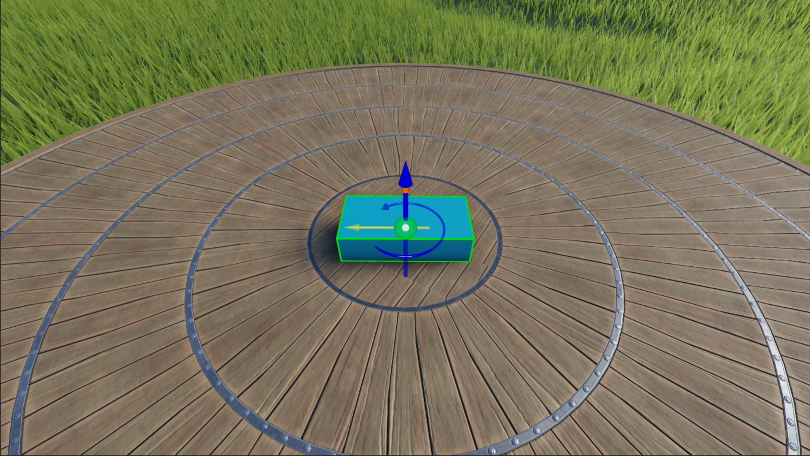
To demonstrate this process, you will add a block to your workspace with an attachment that an AngularVelocity constraint references to spin the block 6 radians per second along the world's Y axis at a constant angular velocity, or about one full rotation.

Add Attachment
You can specify the fixed point to spin an assembly by adding an Attachment object to the assembly, then configuring the attachment's position in the 3D space. The sample Spinning Objects experience places an attachment in the center of a block part so that the constraint can spin the part counterclockwise around the center of itself.
Attachments include visual aids to help you visualize their axes of rotation. The yellow arrow denotes the attachment's primary axis, and the orange arrow denotes the attachment's secondary axis. While neither axis of rotation influences the block's rotation in the steps of this technique, it's important to understand these visual aids for future reference because they can assist you in determining ideal behavior for different types of constraints, such as the HingeConstraint in the next technique.

To add an attachment:
In the Explorer window, insert a block part into the Workspace.

Insert an attachment into the new part.
- In the Explorer window, hover over the part and click the ⊕ button. A contextual menu displays.
- From the menu, insert an Attachment. The attachment displays in the center of the part.
- Rename the attachment to SpinAttachment.


Configure Constraint
Now that your block has a fixed point to spin the block, you can configure the properties of an AngularVelocity constraint to specify the rotational direction, axis or axes to apply a target constant angular velocity, the amount of radians you want the block to spin per second, and the maximum amount of torque the engine can apply for the block to reach a constant angular velocity.
The sample Spinning Objects experience applies up to 1000 Rowton-studs of constant angular force to spin the block 6 radians per second along the world's Y axis at a constant angular velocity. Rowton-studs are Roblox's primary physical units for measuring torque. To reference Roblox physical units and how they convert to metric units, see Roblox Units.
To configure an AngularVelocity constraint:
(Optional) Make the constraint visible in the 3D space so that you can reference its rotational direction.
- In the menu bar, navigate to the Model tab, then the Constraints section.
- If it's not currently enabled, click Constraint Details to display constraint visual aids.

Insert an AngularVelocity constraint into the part.
- In the Explorer window, hover over the part, then click the ⊕ icon. A contextual menu displays.
- From the contextual menu, insert AngularVelocity. The constraint's visual aid displays in the middle of the part.
Assign the part's attachment to the new constraint.
- In the Explorer window, select the constraint.
- In the Properties window,
- Set Attachment0 to SpinAttachment.
- Set AngularVelocity to 0, 6, 0 to spin the part 6 radians per second along the Y axis. Note that if you were to set this property to 0, -6, 0, the block would spin clockwise.
- Set MaxTorque to 1000 to apply up to 1000 Rowton-studs of constant angular force per second to achieve the target angular velocity.
- Keep RelativeTo to World to spin the block relative to the world's position and orientation.
Verify the amount of torque you set spins the block 6 radians per second along the world's Y axis.
In the menu bar, navigate to the Test tab.
In the Simulation section, click the Mode Picker. A dropdown menu displays.
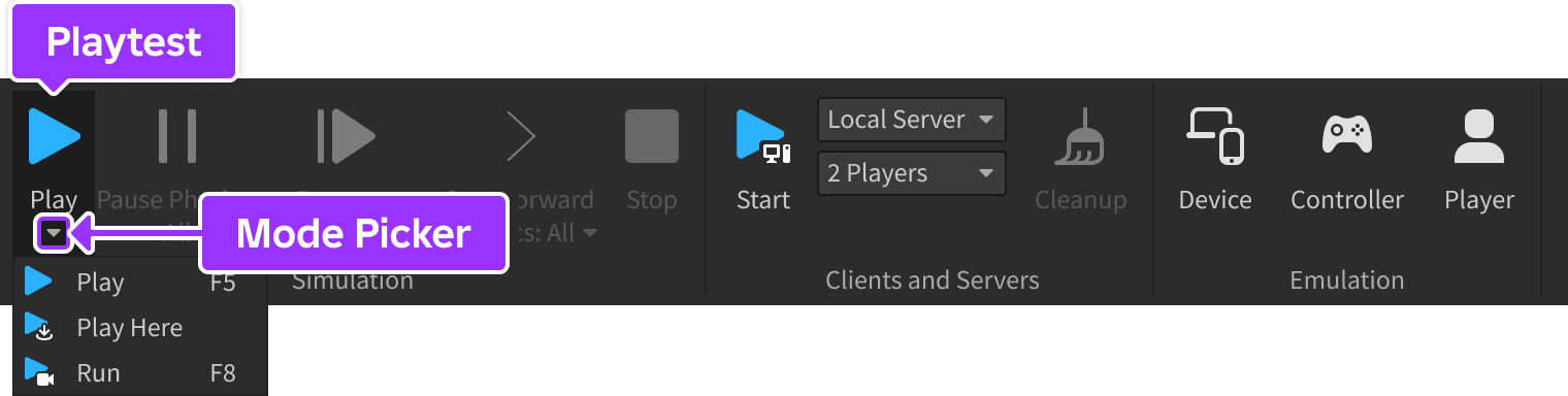
Select Run. Studio simulates the experience at the current camera position without your avatar in the 3D space.


You may need to adjust your torque depending on your block's scale and any oppositional physical forces in your environment. For example, the properties of the AngularVelocity constraint in the sample experience work for a block part with a default size of 4, 1, 2 on a flat platform with a plastic material, and an environment with the classic preset gravity.
However, if your block is a larger size and on grass terrain, you need to increase your AngularVelocity.MaxTorque property because the angular force needs to overcome both the block's mass and friction from the environment. For example, the large block part that's quadruple the size of the sample's part needs at least 300000 Rowton-studs of constant angular force to achieve the set angular velocity!
Using HingeConstraint Constraints
HingeConstraint objects are a type of mechanical constraint that allows two attachments to rotate around one axis, constraining the attachments to the same position and their primary axes in the same direction. When you set HingeConstraint.ActuatorType to Motor, this constraint applies torque on the two attachments with the goal of the attachments reaching and maintaining a constant angular velocity.
Further, when you place attachments into an assembly with two objects, the objects lock together and attempt to spin together according to the attachment's fixed primary axis. If you anchor one of these objects, the angular force continues to spin the other object at a constant angular velocity while the rest of the assembly remains stationary.
For example, to begin spinning a particular object within an assembly, the HingeConstraint constraint needs to know:
- The position where you want the attachments to overlap.
- The point and positive or negative direction to apply an angular force.
- The amount of radians you want the attachment to spin per second.
- The maximum amount of torque the engine can apply for the attachment to reach a constant angular velocity.
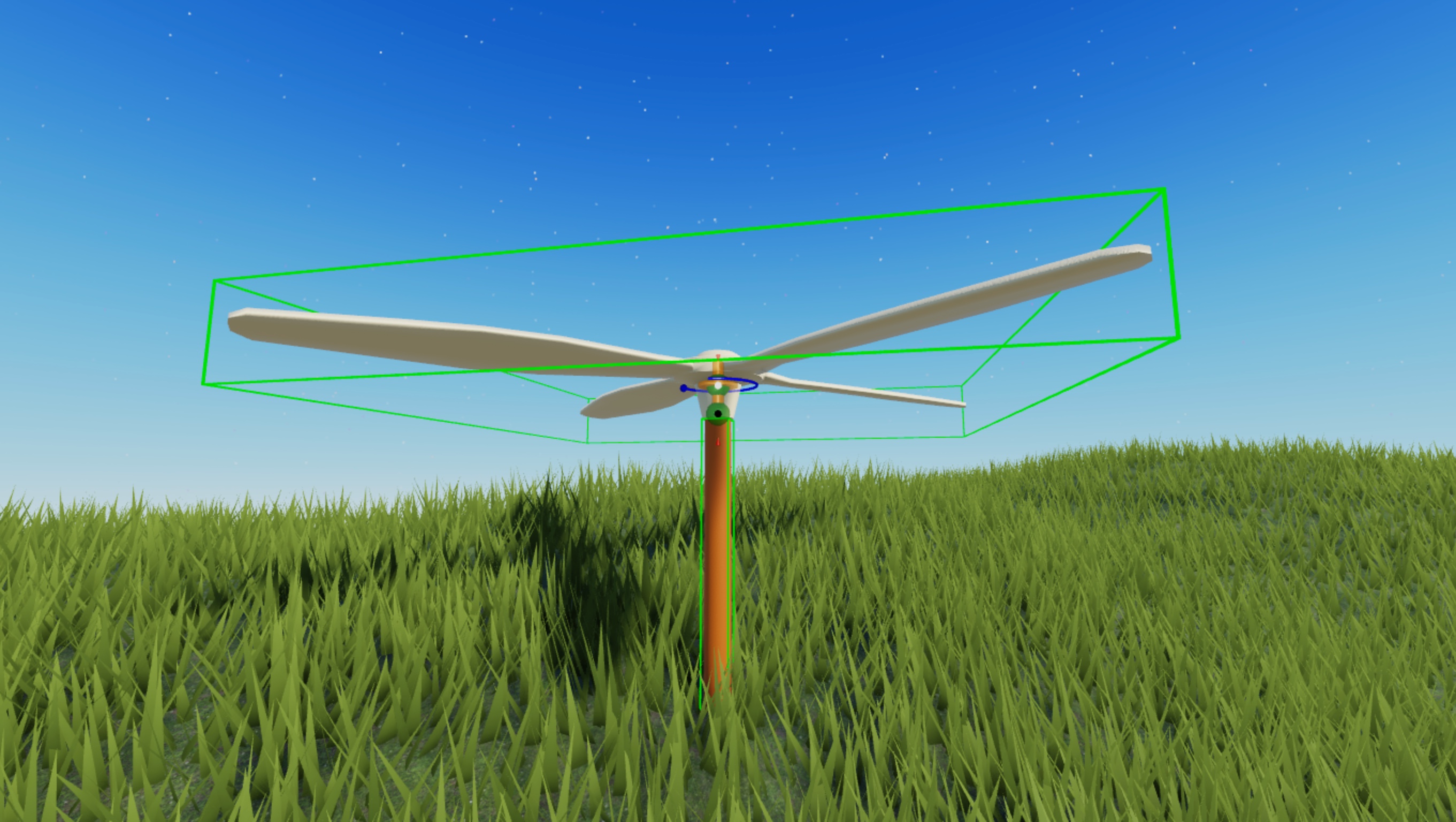
To demonstrate this process, you will add a propeller assembly with two objects to your workspace with attachments in both objects that a HingeConstraint constraint references to spin the propeller 3 radians per second (about half a full rotation per second) along the Y axis at a constant angular velocity while the base of the propeller remains stationary.

Get Propeller Asset
The Creator Store is a tab of the Toolbox that you can use to find all assets that are made by Roblox and the Roblox community for use within your projects, including model, image, mesh, audio, plugin, video, and font assets. You can use the Creator Store to add an individual asset or asset library directly into an open experience.
This tutorial references a propeller model that you can use as you replicate each step of the HingeConstraint technique of spinning objects. You can add this model to your inventory within Studio by clicking the Add to Inventory link in the following component. Once assets are within your inventory, you can reuse them in any project on the platform.
To get this propeller asset from your inventory into your experience:
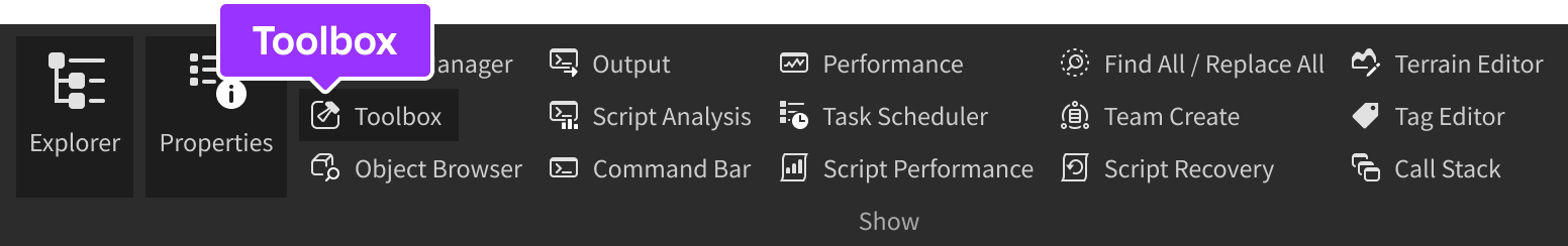
In the menu bar, select the View tab.
In the Show section, click Toolbox. The Toolbox window displays.
In the Toolbox window, click the Inventory tab. The My Models sort displays.
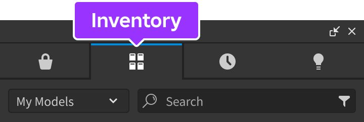
Click the Propeller tile. The model displays in your viewport.


Configure Attachments
You can specify both the position of where you want the attachments to overlap and the direction of rotational movement to spin a particular object within an assembly by adding two Attachment objects to the assembly, then configuring their alignment and orientation in the 3D space.
The sample Spinning Objects experience aligns two attachments near the position of where the unanchored propeller overlaps with the anchored base, and orients their primary axis of rotation upwards so that they spin counterclockwise. The base attachment cannot spin in this example because the base is anchored.
To configure attachments for the hinge constraint:
Insert an Attachment object into Head and Base.
- In the Explorer window, hover over Head and click the ⊕ button. A contextual menu displays.
- From the menu, insert an Attachment.
- Repeat this process for Base.
- Rename both attachments HeadAttachment and BaseAttachment, respectively.

Rotate HeadAttachment and BaseAttachment so that the primary axis of each attachment points upwards on the Y axis. This tells Studio to rotate the attachments counterclockwise.

Move BaseAttachment to the top of Base, and HeadAttachment to the bottom edge of Propeller. This tells Studio where to connect the hinge itself, and overlap both attachments at runtime.


Configure Constraint
Now that your attachments have position to overlap and a direction of rotational movement, you can configure the properties of a HingeConstraint constraint to specify the amount of radians you want the attachment to spin per second, and the maximum amount of torque the engine can apply for the attachment to reach a constant angular velocity.
Similar to the previous technique, the sample Spinning Objects experience applies up to 1000 Rowton-studs of constant angular force to spin the attachment 3 radians per second along the Y axis at a constant angular velocity. However, because the base attachment is in an anchored object, only the propeller's attachment can spin.
To configure a hinge constraint:
Insert a HingeConstraint object into Head.
- In the Explorer window, hover over Head, then click the ⊕ icon. A contextual menu displays.
- From the contextual menu, insert a HingeConstraint.
Assign the propeller's attachments to the new constraint so that the propeller spins in relation to the anchored base.
- In the Explorer window, select the constraint.
- In the Properties window,
- Set Attachment0 to BaseAttachment.
- Set Attachment1 to HeadAttachment. The hinge displays in the viewport.

In the Explorer window, select the constraint, then in the Properties window,
- Set ActuatorType to Motor. New property fields display.
- Set MotorMaxTorque to 1000 to apply up to 1000 Rowton-studs of constant angular force to achieve the target angular velocity.
- Set AngularVelocity to 3 to spin the head of the propeller 3 radians per second.
Verify the amount of torque you set spins the propeller 3 radians per second along the Y axis.
In the menu bar, navigate to the Test tab.
In the Simulation section, click the Mode Picker. A dropdown menu displays.
Select Run. Studio simulates the experience at the current camera position without your avatar in the 3D space.

Applying an Initial Angular Force
Another way of changing an object's angular velocity is by applying an impulse of angular force. After the impulse of angular force, the object either decelerates until it becomes stationary if there is an oppositional force such as friction, or remains in motion with constant velocity if there aren't any oppositional forces.
This technique is useful to spin objects after a significant gameplay or weather event, such as a strong gust of wind, because it provides players instantaneous feedback. To demonstrate, the following subsection teaches you how to spin an assembly with an initial random angular force that you can adapt with new values to meet your own gameplay requirements.
Using ApplyAngularImpulse
The ApplyAngularImpulse method applies torque on an entire assembly to obtain an initial angular velocity before slowing to a stop. To begin spinning the assembly, the method needs to know:
- The assembly to spin.
- The axis to apply torque to reach an initial angular velocity.
- The amount of torque to apply to each axis.
You can define all of these values in a script. For example, the sample script defines the assembly to spin as the script's parent, then it applies a random impulse of angular force between 0 and 100 Rowton-studs on the Y axis.
To spin an assembly using ApplyAngularImpulse:
Insert a sphere part into the Workspace. The sample uses a sphere with a MaterialVariant so you can clearly visualize the sphere's movement.

Insert a script into the new part.
- In the Explorer window, hover over the part and click the ⊕ button. A contextual menu displays.
- From the menu, insert a Script.
Replace the default code with the following code:
