Assembling an asset library is the process of importing and configuring a collection of assets in a central location within your game for easy access and reuse. This process can save you significant time as you prepare to construct your environment, especially if you configure each asset's values to enhance performance and optimize memory usage on mid to low-end devices.
Using the Environment Art - Assembling .rbxl file as a reference, this section of the environmental art curriculum shows you how to assemble an asset library from your polished assets, including step-by-step instructions on:
- Creating custom materials for your terrain from your tileable textures.
- Creating SurfaceAppearance objects for your trim sheet, and applying them to unwrapped meshes in your asset library.
- Setting rendering parameters for your assets to ensure optimal performance across all devices.
- Converting your assets into packages so that you can update and reuse them across all of your projects.
After you complete this section, you will learn how to utilize your asset library in creative ways to replace or convert the greybox environment, and add final touches that enhance the overall 3D space.

Create custom materials
Studio represents custom materials as MaterialVariant objects within the MaterialService. These MaterialVariant objects have four properties that combine the four tileable texture maps to create a high-quality custom material with physical characteristics:
- MaterialVariant.ColorMap – Represents the albedo texture map.
- MaterialVariant.MetalnessMap – Represents the metalness texture map.
- MaterialVariant.NormalMap – Represents the normal texture map.
- MaterialVariant.RoughnessMap – Represents the roughness texture map.
After you supply the texture maps to these properties, you can apply your new custom material to both parts, meshes, and terrain. You can use or modify the sample texture map .png files to create the Lumpy Moss, Flowering Lumpy Moss, Lumpy Moss with Stones, and Stones custom materials within the final sample laser tag environment, or you can use your own that you designed in the previous section of the tutorial.
To create MaterialVariant objects for your tileable textures:
From the Window ⟩ 3D menu, select Material to open the Material Manager.
In the Materials list, select the base material that most aligns with your tileable texture. For example, if you were creating a MaterialVariant object for the Lumpy Moss tileable texture, choose the default ground material so the material inherits its physical properties.
In the upper toolbar, click the ⊕ icon. A new MaterialVariant displays in the palette with an icon in the bottom-right corner that indicates it's a custom material.

In the Inspector, navigate to the General section, then rename the material to align with the name of your tileable texture.

In the Texture Maps section, on the right-hand side of Color, click the Import button. A file browser displays.

In the file browser, select the Albedo texture map .png file for the corresponding tileable texture, then the Open button. The file browser closes, and the new color map displays with its asset ID.
Repeat this process for the Metalness, Normal, and Roughness texture maps. The custom material updates to reflect the texture maps.


In the Overrides section, enable the Set as Override toggle to ensure that when you apply ground to your terrain, Studio uses this custom material.

- OPTIONALIf you are creating a custom material that represents an organic material,
- In the Tiling section, click the Pattern dropdown.
- Select Organic to randomize the output and reduce visible tiling.
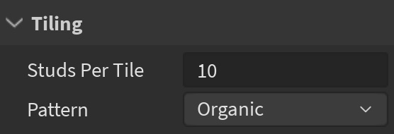
Repeat this process for each tileable texture you want to include in your game.


Create SurfaceAppearance packages
Studio utilizes trim sheets within SurfaceAppearance objects that you can parent to MeshParts that contain UV data. Similar to custom materials, SurfaceAppearance objects have four properties that combine the four trim sheet texture maps to create a high-quality 3D visual surface treatment:
SurfaceAppearance.ColorMap – Represents the albedo texture map. SurfaceAppearance.MetalnessMap – Represents the metalness texture map. SurfaceAppearance.NormalMap – Represents the normal texture map. SurfaceAppearance.RoughnessMap – Represents the roughness texture map.
After you supply the texture maps to these properties, you can make the SurfaceAppearance object a child of a MeshPart with uv data that maps to your trim sheet, and the uv data automatically applies to the parent mesh. It's for this reason that it's useful to make the SurfaceAppearance object a package so that you can reuse the same SurfaceAppearance object across all of your modular assets and props. For example, the following meshes all have uv data that maps to the same trim sheet layout that's represented within a single SurfaceAppearance object package.

You can use or modify the sample texture map .png files to create a SurfaceAppearance object that respects the uv data for the sample modular assets and props within the final sample laser tag environment, or you can use your own that you designed in the previous section of the tutorial that apply to your own modular assets and props.
To create SurfaceAppearance packages that you can child to your modular kit and props:
Insert a SurfaceAppearance object into Workspace.
Select the SurfaceAppearance object, then in the Properties window, select the ColorMap property. A pop-up displays.
Click the Add Image… button. A file browser displays.

Select the Albedo texture map for the corresponding tileable texture, then the Open button. The file browser closes, and the ColorMap property updates with a new asset ID.
Repeat this process for the MetalnessMap, NormalMap, and RoughnessMap properties, selecting their respective texture maps from the file browser.
In the Explorer window, right-click the SurfaceAppearance object, then select Convert to Package from the contextual menu. The Convert to Package dialog displays.
Fill out the Title and Description fields, set the ownership to yourself or a group, then click the Submit button. Once complete, a chain link symbol displays over the SurfaceAppearance object's icon to identify it as a package.

- OPTIONALSelect the SurfaceAppearance object's child PackageLink object, then in the Properties window, enable AutoUpdate to automatically update the package if you make any modifications to the SurfaceAppearance object.


Import modular assets and props
Studio represents the modular assets and props that you import as Model objects with child MeshParts for each component of the asset. For example, if you import a wall section with a top trim, bottom trim, and wall component, Studio represents the .fbx or .obj file as a Wall_Section Model with separate child Top_Trim, Bottom_Trim, and Wall MeshParts.

Using the Importer, you can import the sample modular kit and props into Studio for use in your asset library, or you can import any assets you designed in the previous section of the tutorial. For more information on this tool's functionality, see Importer.
To import your modular assets and props into the game:
From the File menu, select Import. A file browser displays.
Select a .fbx file for either a modular asset or prop.
Verify the object preview and check that the import settings are correct for your object.

Verify any warning or error messages.
Click Import. The asset displays in the Explorer window and in the viewport.
Repeat this process for each modular asset and prop.
Move all of your assets into one area of your game near your greybox geometry. This zone is your asset library.

Apply SurfaceAppearance data
When you go through the process of unwrapping the UVs of a mesh in third-party modeling software, the software stores the UV data within the mesh's .fbx or .obj file. When you import that mesh into Studio, the resulting MeshPart object retains that data, but you still need to apply a SurfaceAppearance object with texture map properties from your trim sheet in order to display your trim textures on the asset.
To apply SurfaceAppearance texture map data to unwrapped meshes in your asset library:
- In the Explorer window, click your SurfaceAppearance package, then press CtrlD (⌘D) to duplicate it.
- Child the duplicate SurfaceAppearance package to either a modular asset or a prop. The asset applies its UV data to the texture maps and displays its visual treatment.
- Repeat this process for each modular asset and prop.
Set physics and rendering parameters
Now that you have your assets within Studio, it's important to set physics and rendering parameters that allow the assets to retain the highest possible visual quality across devices with memory and GPU limitations. In general, the more closely you adhere to the guidance in this section, the more performant you make your game. However, it's important to carefully consider the context of where you plan to place each asset within the overall environment to ensure you maintain your aesthetic goals and gameplay requirements.
Anchored
The BasePart.Anchored property determines whether the Roblox Engine's physics system affects the position of the object. When you enable this property for a Part or MeshPart, it removes the object from the physical calculations of the dynamic simulation that's always running in game, meaning the object will never change position due to gravity or collision from other objects.
Objects that don't simulate a physics response are cheaper to render because they don't take up the GPU that's necessary for those physics calculations. When you free up GPU, you improve performance for your game, especially on low-end devices that need to save GPU for fast-paced gameplay. It's for this reason that every asset aside from doors in the final sample laser tag environment are anchored.
CanCollide
The BasePart.CanCollide property determines whether the object can physically interact with other objects. When you enable this property for a Part or MeshPart, the object is impenetrable, and the Roblox Engine accounts for it in physics calculations. These calculations can impact your game's performance when there are many objects the engine must consider in its physics calculations.
To alleviate some of this impact on performance, disable this property for objects that the user will never interact with. For example, the final sample laser tag environment disables this property for all foliage.

CanTouch
The BasePart.CanTouch property determines if Touched and TouchEnded events fire on the object. When you enable this property for a Part or MeshPart, the Roblox Engine checks the object's touch event state to see if it needs to trigger or stop an event.
This process happens for every single frame, which can take up a significant amount of memory if the engine needs to check the touch event state for many objects at once. To alleviate some of this impact on memory, only enable this property for objects that must trigger an event.
CanQuery
The BasePart.CanQuery property determines whether the Roblox Engine considers the object during spatial query operations, such as raycasting. Studio enables this property for every Part or MeshPart by default, meaning that the engine checks to see if each object needs to call a spatial query operation. This process occurs for every single frame, which can take up a significant amount of memory when the engine needs to make these checks for many objects at once.
For this reason, it's recommended to disable this property for objects that the Roblox Engine doesn't need to consider for spatial query operations. When making decisions about where to disable this property, consider how each asset impacts gameplay. For example, the final sample laser tag environment keeps this property enabled for every wall in the building because the engine needs to account for these surfaces as users fire lasers from their laser tag gun. If the engine doesn't account for these assets, then the laser would shoot straight through the building as though it wasn't there at all.
CastShadow
The BasePart.CastShadow property determines whether the object casts a shadow. When you enable this property for a Part or MeshPart, the Roblox Engine calculates every vertex location of the object at runtime, then draws a raycast from the sun to any of its neighboring objects until it collides with another object to create the shadow.
These calculations can come at a performance cost, especially when you have many objects of geometric complexity. This is because objects with geometric complexity have more polygons than objects that are geometrically simple, meaning they have more vertices that the engine needs to calculate for the object's shadow. The fewer polygons in an object, the faster the operation and cheaper its shadow.

Shadows can provide a great sense of realism to objects with 3D geometrical depth, so when you're deciding where to disable this property, consider where objects provide a significant visual improvement to the environment, and where users will notice missing shadows. For example, the complex shadows of foliage can provide a great sense of immersion in the outdoor space where users are likely to see them, but that same immersion isn't necessary for the foliage that peaks through the ceiling that users will never interact with.


DoubleSided
The MeshPart.DoubleSided property determines whether to render both faces or polygons in the mesh. When you enable this property for a planar MeshPart, such as leaves, hair, or cloth cards, the Roblox Engine renders both faces or polygons in the mesh to allow users to see the fullness of the object no matter what angle they are looking at the object. For example, the following tree leaves are single-sided planar meshes, and when you enable this property, any of the leaves that face away from the camera become visible to the user.


This property is useful for adding realism to your environment, but it comes at a performance cost because the engine needs to render the object's polygons twice: once for the direction that faces the user's camera, and again for any meshes that face away from the user's camera. To alleviate some of this impact on performance, the final sample laser tag environment only enables this property for foliage because it has a strong visual impact for realism in the 3D space.
CollisionFidelity
The MeshPart.CollisionFidelity property determines how closely the physical hitbox of a mesh or union matches its visual representation. By default, this setting renders a hitbox that's roughly the same as the polygonal shape of the mesh, meaning that where users collide with the object is similar to the actual geometry of the mesh. For example, the castle mesh in the following images has a default hitbox that almost matches the shape of its geometry.


You can set this property to a different value to reduce the precision of a mesh's hitbox. For example, when you set this property to Hull, the Roblox Engine significantly reduces the vertices of the mesh's hitbox, and when you set this property to Box, the engine reduces the mesh's hitbox to a cube that surrounds the mesh. In addition, if you want to increase the precision of a mesh's hitbox, you can set this property to PreciseConvexDecomposition to increase the amount of vertices in the hitbox.


Similar to BasePart.CastShadow, the more vertices the Roblox Engine needs to render, the higher the performance cost. For this reason, it's important to consider how you want users to interact with each mesh to see if you can reduce the amount of vertices the engine needs to render for the mesh's hitbox. In cases where it isn't necessary for a hitbox to be precise, set this property to either Box or Hull.
To demonstrate this concept, reference the following images that display the hitbox of every mesh of the wall model that provides a rise in elevation between the first and second floor of the final sample laser tag environment. The default hitbox for the main wall has a lot of unnecessary geometry when it only needs to provide a surface to prevent the user from moving in that direction. If you set the property to Box for this mesh, you can remove this redundant geometry while keeping the purpose of the hitbox intact.


As you're making these decisions, it's important to consider how changing the default value may negatively affect users as they're navigating your environment. For example, if you set the property to Box for the trim meshes of the wall model, users would collide with the hitbox if they try to jump near the wall. Instead, set these meshes to Hull so you reduce its vertex count while keeping the hitbox closer to the shape of the mesh's geometry.


Note that it can be important to have a hitbox that precisely conforms to the shape of your mesh, especially when you need to control exactly how users collide with its shape. For example, in the final sample laser tag environment, it's important that users only collide with the edges of the doorway and not the doorway itself, otherwise they would never be able to enter or exit a combat pocket.

RenderFidelity
The MeshPart.RenderFidelity property determines the mesh's level of detail that displays to the user. When you set this property to Enum.RenderFidelity.Automatic, the Roblox Engine reduces the mesh's fidelity the further the user is from the mesh, and when you set this property to Enum.RenderFidelity.Precise, every vertex of your mesh renders exactly as you intend no matter the distance between them.
The more objects the engine must render precisely to the user from any distance, especially if they have a high vertex count, the higher the performance cost. To alleviate some of this impact on performance, set this property to Enum.RenderFidelity.Performance for objects with geometric complexity, such as foliage in the sample asset library, because they don't need to display in their entirety from a distance for any gameplay requirement. This reduces your game's polygon count without yielding overall visual quality.
Convert assets into packages
Now that all of your modular assets are in Studio with rendering parameters that are set up to retain their high visual quality for all users, it's time to convert them into packages. It's important to convert your assets into packages because it allows you to reuse them repeatedly throughout your current game and other projects. In addition, you can easily make edits to a package that instantly populate to all of its instances, saving you a lot of time in the iteration process.
Because your SurfaceAppearance objects are already packages, when you convert your Model objects into packages, they become nested packages. Nested packages allow you to maintain complex hierarchies of child objects that you can modify independent of the Model object package. This allows you greater control over the individual components of your assets.

To convert your modular assets and props into packages:
In the Explorer window, right-click a modular asset or a prop, then select Convert to Package from the contextual menu. The Convert to Package dialog displays.
Fill out the Title and Description fields, set the ownership to yourself or a group, then click the Submit button. Once complete, a chain link symbol displays over the model's icon to identify it as a package.

Repeat this process for each modular asset and prop.

Once you are happy with the overall layout of your asset library, you can move on to decorating the environment with your newly polished assets, and configuring additional elements of the 3D space to bring your world to life.