Moving objects are objects that move on one or more axes within the 3D space. Using the built-in power of Roblox's simulation engine, you can make objects move and interact with their environment in a way that emulates real-world physical behavior that's familiar and intuitive to players, such as gravity, aerodynamics, and friction.
Using the Moving Objects .rbxl file as a reference, this tutorial explains how physical forces impact linear motion in Studio, and shows you various techniques to move objects from point A to point B in your games with different movement behavior, including guidance on:
- Using a LinearVelocity mover constraint to move an entire assembly at a constant linear velocity.
- Using a PrismaticConstraint to constrain an assembly to a single axis and move it at a constant linear velocity relative to a point in the 3D space.
- Using the ApplyImpulse method to move an assembly with an initial impulse of force so that the assembly slowly decelerates over time.
Linear motion and physical forces
Roblox Studio is a real-world simulation engine that emulates physical behavior in real time, so in order to predict how objects moving linearly can behave in games, it's important to have a high-level understanding of how objects move in real life with linear motion.
Linear motion is movement along an axis. For example, when a block has linear motion, it moves along a set axis.

Linear motion cannot exist without external, physical forces pushing or pulling objects to move. According to Newton's first law of motion, stationary objects remain stationary and moving objects remain in motion with a constant velocity unless they are acted on by an external force. For example, a stationary block remains stationary unless a physical force like wind pushes it to move.
Force is the measure of the direction and magnitude of a physical push or pull that causes objects to change their linear velocity along an axis. A change in velocity is known as acceleration. This concept is particularly important for objects to move in Studio; the more force you apply to objects, the more quickly they accelerate.
This is because the force needs to be greater than any physical forces pushing back against the object, such as gravity or friction. For example, if you were to place the block on a metal plate, the physical force of the wind needs to overcome the amount of friction from the metal plate to continue accelerating the block. If the wind's force is not much greater than the friction from the metal plate, the block accelerates, just more slowly than the previous example.

Linear velocity is the measure of an object's movement, or how fast the object changes its position along an axis over a period of time. Studio measures linear velocity according to how many studs an object moves per second. Studs are Roblox's primary physical units for measuring length, and each stud equates to about 28cm in the real world.

Understanding linear velocity is important for designing gameplay because it helps you determine how much force you need in order to achieve a particular speed for your moving objects. For instance, when you want to propel objects upward, it's important to consider how you must adjust your force to overcome gravity within the environment so that the objects move accurately.
The following sections dive deeper into these concepts as you learn how to move objects at either a constant or initial linear velocity with the necessary force to overcome any oppositional physical forces within the environment. As you review these physics concepts with the upcoming techniques, you can more accurately predict how to adjust property values to achieve any ideal linear movement behavior in Studio.
Maintain a constant linear velocity
For an object to reach and maintain a constant linear velocity, it needs a force to overcome any oppositional physical forces that either decelerate the object's linear velocity, or cause the object to remain stationary. For example, if you want an object to have a linear velocity of [0, 12, 0] in Studio, you need enough force for the object to reach and maintain 12 studs per second along the Y axis in its environment.
The amount of force necessary not only depends on oppositional physical forces within the environment itself, such as gravity and friction, but also on the object itself. For example, if you have two objects of the same shape that are moving on the same axis, the object with the larger amount of mass requires more force to achieve the same linear acceleration.
The following subsections use assemblies of different shapes and sizes to teach you how to move either an entire object or only a portion of the object at a constant linear velocity. As you experiment with different property values, you will learn how to estimate the maximum amount of force you need for assemblies in your own games.
Use LinearVelocity constraints
LinearVelocity objects are a type of mover constraint that apply force on an entire assembly to maintain a constant linear velocity. By not locking the assembly's position to an axis during its motion, the assembly is free to rotate as it collides with other objects in the 3D space. This type of movement leads to surprising gameplay scenarios that are more difficult for players to predict.
To begin moving the assembly, the LinearVelocity constraint needs to know:
- The point and positive or negative direction to apply a force.
- The amount of studs you want the assembly to move per second.
- The maximum amount of force the engine can apply for the assembly to reach the constant linear velocity.
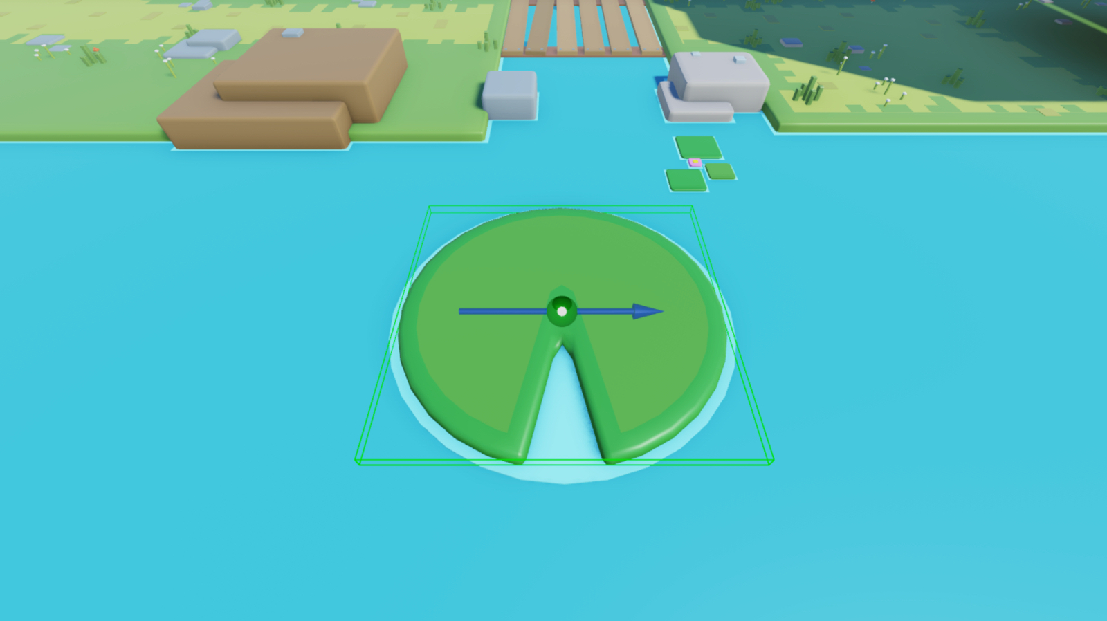
To demonstrate this process, you will configure a lily pad with an attachment that a LinearVelocity constraint references to move the lily pad 15 studs per second along the world's negative X axis at a constant linear velocity.

Add attachment
You can specify the point to apply force by adding an Attachment object to the assembly, then configuring the attachment's position in the 3D space. The sample Moving Objects game places an attachment in the center of the lily pad so that the constraint can move the mesh from the attachment along a particular axis.
Attachments include visual aids to help you visualize their axes of motion. The yellow arrow denotes the attachment's primary axis, and the orange arrow denotes the attachment's secondary axis. While neither axis of motion influences the lily pad's movement in the steps of this technique, it's important to understand these visual aids for future reference because they can assist you in determining ideal behavior for different types of constraints, such as the PrismaticConstraint in the next technique.

To add an attachment:
In the Explorer window, expand the LinearVelocityExample folder, then expand its child LilyPad_DIY model.
Insert an attachment into the Pad mesh.
- Hover over the mesh and click the ⊕ button. A contextual menu displays.
- From the menu, insert an Attachment. The attachment displays in the center of the part.
- Rename the attachment to MoveAttachment.


Configure constraint
Now that your mesh has a fixed point to move the lily pad, you can configure the properties of a LinearVelocity constraint to specify the direction and magnitude for the constant linear velocity, the amount of studs you want the mesh to move per second, and the maximum amount of force the engine can apply for the mesh to reach a constant linear velocity.
The sample Moving Objects game applies up to 5000 Rowtons of constant force to move the lily pad 15 studs per second along the world's negative X axis at a constant linear velocity. Rowtons are Roblox's primary physical units for measuring force. To reference Roblox physical units and how they convert to metric units, see Roblox Units.
To configure a LinearVelocity constraint:
To make the constraint visible in the viewport so that you can reference its linear direction, enable Show Constraint Details from Studio's View menu.
Insert a LinearVelocity constraint into the Pad mesh.
- In the Explorer window, hover over the mesh, then click the ⊕ icon. A contextual menu displays.
- From the contextual menu, insert LinearVelocity.
Assign the mesh's attachment to the new constraint.
- In the Explorer window, select the constraint.
- In the Properties window,
- Set Attachment0 to MoveAttachment.
- Set MaxForce to 5000 to apply up to 5000 Rowtons of constant force to achieve the target linear velocity.
- Keep RelativeTo to World to move the lily pad relative to the world's position and orientation.
- Set VelocityConstraint to Line to constrain the force along a line from the attachment.
- Set LineDirection to -1, 0, 0 to move the lily pad along the world's negative X axis. Note that if you were to set this property to 1, 0, 0 the lily pad would move along the world's positive X axis.
- Set LineVelocity to 15 to move the lily pad 15 studs per second.
Verify the amount of force you set moves the mesh 15 studs per second along the world's negative X axis.
Select the Run simulation mode from the mezzanine's dropdown menu and click the Play button to begin. Studio simulates the game at the current camera position without your avatar in the 3D space.


Use PrismaticConstraint constraints
PrismaticConstraint objects are a type of mechanical constraint that create a rigid joint between two attachments, allowing their parent assemblies to move along one axis relative to each other. By locking both assemblies' position to a single axis, each assembly is only able to rotate if they rotate together in the same direction.
This type of movement leads to stable gameplay scenarios that are easier for players to predict. For example, the sample Moving Objects game uses PrismaticConstraint objects to move log platforms that players can use to carefully cross a giant river.
When you set PrismaticConstraint.ActuatorType to Motor, this constraint applies force on the two attachments with the goal of the attachments reaching and maintaining a constant linear velocity. If you anchor one of the attachments' parent assemblies, the force continues to move the unanchored assembly at a constant linear velocity while the anchored assembly remains stationary.
To begin moving the assembly, the PrismaticConstraint constraint needs to know:
- The point and positive or negative direction to apply a force.
- The amount of studs you want the attachments to move per second.
- The maximum amount of force the engine can apply for the attachments and their parent assemblies to reach a constant linear velocity.
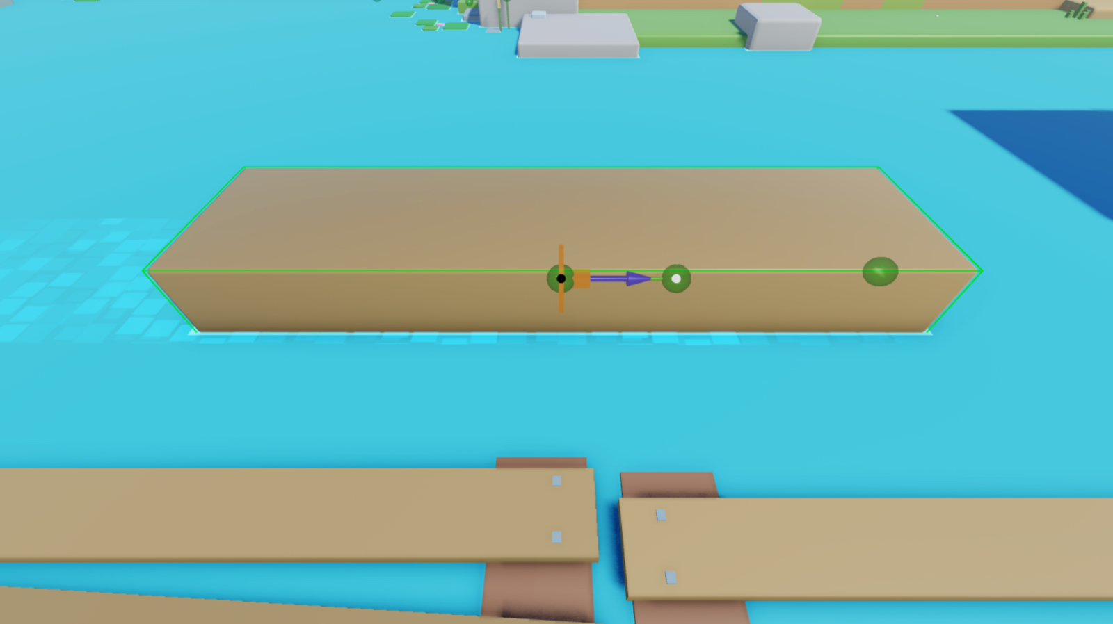
To demonstrate this process, you will configure a log assembly with two objects that have child attachments that a PrismaticConstraint references to move the log 40 studs per second along the world's negative X axis at a constant linear velocity.

Configure attachments
You can specify the direction to move a particular object within an assembly by adding two Attachment objects to the assembly, then configuring their alignment and orientation in the 3D space. The sample Moving Objects game aligns two attachments along the world's X axis near the position of where the unanchored log overlaps with the anchored part, and orients each attachment's primary axis to face the world's negative X axis.
When you configure your PrismaticConstraint constraint in the next section, it will move the log in relation to the anchor part. In other words, the log will move away from the stationary part that cannot move because it's anchored in the 3D space.
To configure attachments for the prismatic constraint:
In the Explorer window, expand the PrismaticConstraintExample folder, then expand its child Log_DIY model.
Insert an attachment into the Log mesh.
- Hover over the mesh and click the ⊕ button. A contextual menu displays.
- From the menu, insert an Attachment. The attachment displays in the center of the part.
- Rename the attachment to LogAttachment.

Using the same process, insert an attachment into the Anchor part, then rename the attachment AnchorAttachment.

Using the View Selector tool as a reference for the world's coordinates, rotate LogAttachment and AnchorAttachment until each attachment's primary axis faces the world's negative X axis

Reposition AnchorAttachment so that both attachments are aligned on the world's X axis.


Configure constraint
Now that your attachments are aligned on the same axis and face the same direction you want the log to move, you can configure the properties of a PrismaticConstraint constraint to specify whether to apply the target constant linear velocity in the positive or negative direction of each attachment's' primary axis, the amount of studs you want the attachments to move per second, and the maximum amount of force the engine can apply for the log to reach a constant linear velocity.
While you can choose different values for your own use cases, the sample Moving Objects game applies up to 50000 Rowtons of constant force to move the attachments 40 radians per second along the world's negative X axis at a constant linear velocity. However, because the anchor attachment is in an anchored object, only the log's attachment can move.
To configure a prismatic constraint:
Insert a PrismaticConstraint object into the Log mesh.
- In the Explorer window, hover over the mesh, then click the ⊕ icon. A contextual menu displays.
- From the contextual menu, insert a PrismaticConstraint.
Assign the log's attachments to the new constraint so that the log moves in relation to the anchored block part.
- In the Explorer window, select the constraint.
- In the Properties window,
- Set Attachment0 to AnchorAttachment.
- Set Attachment1 to LogAttachment. The constraint displays in the viewport.

In the Explorer window, select the constraint, then in the Properties window:
- Set ActuatorType to Motor. New property fields display.
- Set MotorMaxForce to 50000 to apply up to 50000 Rowtons of constant force to achieve the target linear velocity.
- Set Velocity to 40 to move the log 40 studs per second.
Verify the amount of force you set moves the log 40 studs per second along the world's negative X axis.
Select the Run simulation mode from the mezzanine's dropdown menu and click the Play button to begin. Studio simulates the game at the current camera position without your avatar in the 3D space.

Apply an initial linear force
Another way of changing an object's linear velocity is by applying an impulse of force. After the impulse of force, the object either decelerates until it becomes stationary if there is an oppositional force such as friction, or remains in motion with constant linear velocity if there aren't any oppositional forces.
This technique is useful to move objects after a significant gameplay event, such as an explosion or impactful collision, because it provides players instantaneous feedback. To demonstrate, the following subsection teaches you how to launch a player's character upward toward the sky when they collide with a jump pad with an initial impulse that you can adapt with new values to meet your own gameplay requirements.
Use ApplyImpulse
The ApplyImpulse method applies force on an entire assembly to obtain an initial linear velocity before slowing to a stop when there are oppositional forces. To begin moving the assembly, the method needs to know:
- The assembly to move.
- The axis to apply force to reach an initial linear velocity.
- The amount of force to apply to each axis.
You can define all of these values in a script. For example, the sample script defines the assembly to move as the player character's Humanoid object, then it applies an impulse of force that's 2500 Rowton-seconds to launch the player upwards on the world's positive Y axis. Note that player characters have different amounts of mass, so you may need to increase and balance this force to launch every player without launching player characters with smaller amounts of mass too high.
To move an assembly using ApplyImpulse:
In the Explorer window, expand the ApplyImpulseExample folder, then expand its child JumpPad_DIY model.
Insert a script into the JumpPad part.
- Hover over the part and click the ⊕ button. A contextual menu displays.
- From the menu, insert a Script. The attachment displays in the center of the part.
- Rename the script to JumpScript.
Replace the default code with the following code:
local volume = script.Parentlocal function onTouched(other)local impulse = Vector3.new(0, 2500, 0)local character = other.Parentlocal humanoid = character:FindFirstChildWhichIsA("Humanoid")if humanoid and other.Name == "LeftFoot" thenother:ApplyImpulse(impulse)endendvolume.Touched:Connect(onTouched)