Dynamic heads are character heads that contain components that allow you to:
- Set default custom facial expressions.
- Equip face accessories, such as eyebrows and eyelashes, that deform with your facial expressions.
- Trigger emotes that combine both face and body animations.
You can create or modify an existing model to become a dynamic head in third-party modeling software, such as Blender or Maya. When creating a dynamic head, your character body model must meet the following requirements:
- The character body must follow Roblox's modeling requirements and include appropriate head geometry, such as eyes, a mouth, and teeth.
- The character body's head must include a rig, or internal joint structure, to drive the various deformation of vertices to create facial expressions.
- The character body must have their facial poses saved to the animation timeline and mapped to the head mesh. Typical dynamic heads include 50 standard base poses that allow for a diverse range of expressions.
To help you meet these requirements, this tutorial covers the processes of adding facial joints, posing them into facial expressions, and mapping 5 basic FACS poses on a Cubie reference character in Blender, as well as how to export the model for import into Studio.
Reference files
The following dynamic head reference files include all checkpoint references throughout this tutorial:
| Reference files | Description |
|---|---|
| Cubie-Model-Only.blend | A Blender project file containing a Cubie character model with a standard R15 rig without facial data. |
| Cubie-Eye-Bones-Skinned.blend | A Blender project file containing the example Cubie character model with skinned eye joints without posing or mapping data. |
| Cubie-Eye-Poses-Mapped.blend | A Blender project file containing the Cubie character model with the 5 example poses saved and mapped. |
| Cubie-Complete.fbx | A Cubie character model with a fully rigged face and over 50 poses saved and mapped. You can import this file into Studio or open it in your preferred 3D modeling software. |
| Cubie-Texture_ALB.png | A Cubie texture image file. After you import the Cubie model into Studio, you can add this file as the head part's TextureID. |
| Cubie-Complete.ma | A Cubie Maya project provided as additional reference. |
Modeling requirements
Many character body models that include a head with distinct facial features require minor modeling adjustments in order to be compatible as a dynamic head. When modeling your avatar characters, verify that each head mesh meets avatar character body specifications for Studio import, as well as the following requirements:
- Face parts - Ensure that you include distinct face features, such as eyes, upper teeth, lower teeth, and a tongue.
- Lip vertices - If you want your character to use its mouth, separate the lip vertices so that the mouth can open.
- Inner components - If your character has inner mouth components, such as a tongue and teeth, model a mouth bag within the head mesh to contain these features. If your character uses eye sockets, model a similar eye bag to contain these features.
- No extra data - Ensure that all children face parts of the Head_Geo don't contain history or frozen transformations.
- Outer cage - Make sure the character model has an outer cage to support face accessories and layered accessories. For more information, see Character body specifications - Inner and outer cages.
You can follow along the rest of this head creation process using a rigged Cubie character that meets these modeling requirements. This version doesn't include any facial rigging or pose data so you can use it as starting point for this tutorial.
Rig and skin the head
Rigging is the process of connecting a mesh with an internal rig so that mesh surfaces can rotate and move as joints rotate and move, and skinning is the process of assigning which parts of the mesh surface move and rotate with specific joints. Dynamic heads require both processes so that surfaces of the head mesh can move with joints to create facial expressions.
The following instructions focus on rigging and skinning Cubie's eyes and eyelids, but you can apply these techniques to the rest of the character's facial features that require articulation, such as the character's mouth, cheeks, and jaw. After adding joints and applying skinning data, you can then create controls to help make the posing process more efficient.
Add joints
Each poseable face feature of your head typically requires at least one joint, but complex features, such as eyes and mouth, might require several joints to make certain poses possible. Unlike the rest of the character's body, Studio doesn't require a specific joint hierarchy for a dynamic head. However, in order for the facial rig to work properly, the rig must include a RootFaceJoint joint and additional face joints to drive the bending and deformation of the face geometry.
The specific head joints your character requires depend on the poses you intend for your character. The following examples cover the process for adding 1 joint for each eye and 4 joints for the eyelids to allow for blinking, winking, and gaze direction. When creating a face rig, use less than 50 face joints where possible and keep the joints organized and specific for their associated facial features. In general, high numbers of vertices and joints can impact your game's performance.
RootFaceJoint
The RootFaceJoint is a joint that is parented under the R15 rigging armature's head joint. This root joint must parent all other face joints. In Blender, you can quickly add a joint by extruding a child joint from the head joint, then mapping the joint name as a property in the Head_Geo mesh.
The RootFaceJoint object is commonly named DynamicHead in the reference templates and examples, but you can use any name as long as you map the root joint in custom properties. This allows Studio to properly locate that joint and hide all of the children joints within the FaceControls instance on import.
To add a RootFaceJoint object:
In Blender, open the rigged Cubie character project.
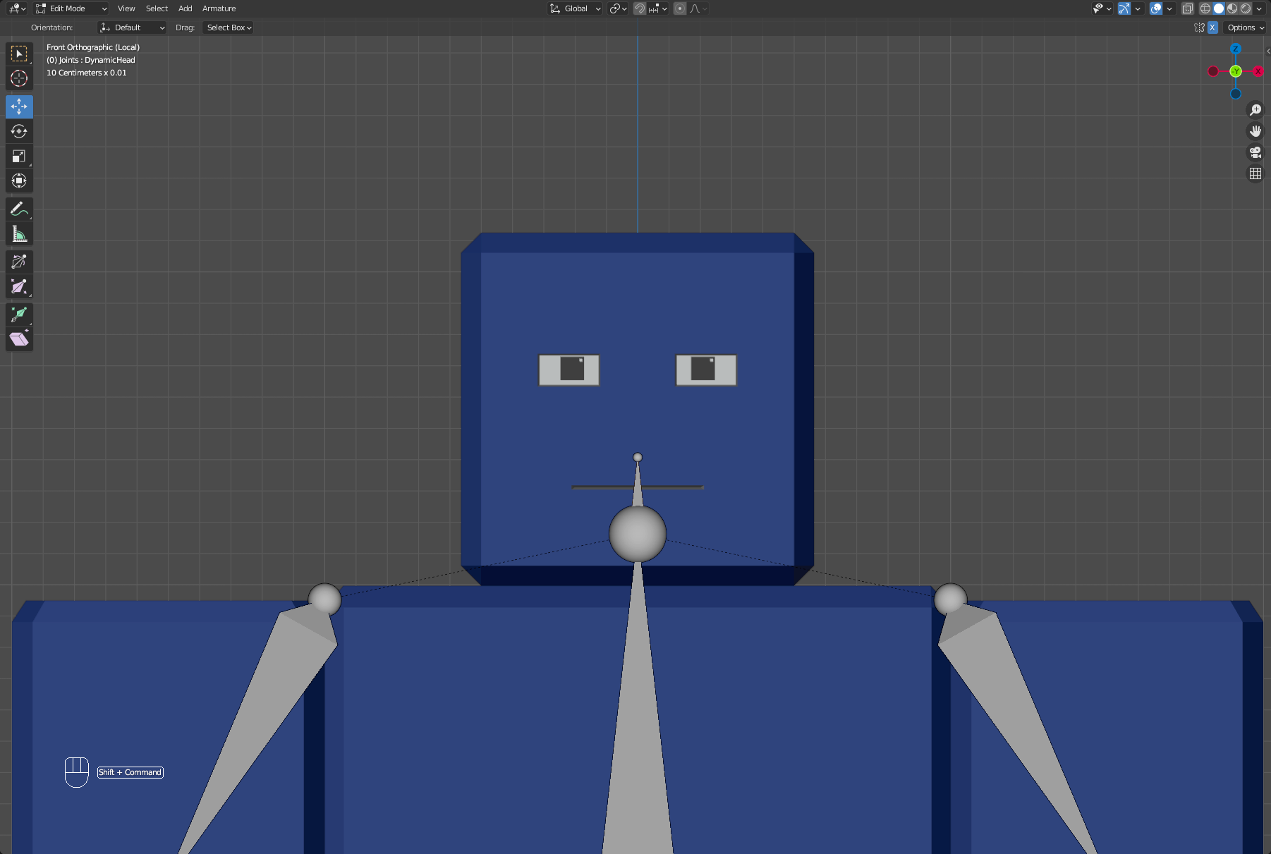
Click on any joint to select the armature, then switch to Edit mode.
In the Outliner, click on the Head joint.
In the viewport, press E and drag your mouse up to extrude an additional child joint from the Head joint.
Back in the Outliner, rename this joint DynamicHead. You will reference this joint by name later in the mapping section.

Eyes
Each eye requires one joint each, though you might opt to create a controller joint later that can control both eyes at the same time. To ensure that you position your joints symmetrically, you can enable X-Axis symmetry in the top-right of the viewport. This moves joints that share the same name with opposing suffixes along the X-axis.
To add joints to the character eyes:
While still in Edit mode, navigate to the topbar of the viewport, then click Add > Single Bone. Do this twice.
Rename one joint LeftEye, and rename the other RightEye.
Adjust the joints so that they are front-facing, horizontal, and around the iris of the character's eyes:
- In the top right corner of the viewport, enable X-Axis symmetry.
- Using the Move tool, position the left or right joint centered at the model's eyes.
- Extend the Item panel, then with the joints selected:
- Copy the Head Y location to the Tail Y location.
- Set Tail Z to 0.2 centimeters to set the Tail Z coordinates with a 0.2 centimeters offset from the Head Z coordinates.
Parent the new joints to your RootFaceJoint.
- Hold Shift and click both LeftEye and RightEye joints.
- While still holding Shift, click the DynamicHead joint.
- Right-click in the viewport, then select Parent > Make > With Offset from the contextual menu.
Eyelids
When adding joints, you can quickly create joints parented under the RootFaceJoint joint by selecting existing facial joints and duplicating them. This automatically creates joints parented under the RootFaceJoint joint.
To add joints to the character eyelids:
While still in Edit mode, hold Shift and click both LeftEye and RightEye joints.
Hold Shift + D and click to duplicate the joints in the same position. Do this four times to create 8 total new joints.
With X-Axis symmetry still enabled, position each joints at the corners of the eyes.
In the Outliner, rename all joints to reflect their specific position using the following names:
- LeftUpperOuterEyelid
- RightUpperOuterEyelid
- LeftLowerOuterEyelid
- RightLowerOuterEyelid
- LeftUpperInnerEyelid
- RightUpperInnerEyelid
- LeftLowerInnerEyelid
- RightLowerInnerEyelid


Skin joints
You can apply skinning data to a character rig using several methods. The following example uses Blender's Weight Paint mode to paint which vertices a single joint can control. Skinning is typically a time consuming step for complex characters and a background in skinning and facial posing is recommended.
When applying detailed or shared influences for complex models, it's recommended to enable Auto Normalize to prevent influence conflicts between joints.
Eyes
Both eyes in the example project require full influences on the pupil within the eye geometry. Depending on the design of the eyes, you might need to adjust influences to create realistic eye poses.
To add influence to your eye joints:
Disable X-Axis symmetry so that you are only influecing the LeftEye joint.
Switch to Object mode, click any joint to select the armature, then hold Shift and click the Head_Geo mesh.
Switch to Weight Paint mode, then in the top right corner of the viewport, enable Wireframe mode to better visualize the vertices.
Hold Shift + Ctrl and click the LeftEye joint to select it. The name of the currently selected joint displays on the top left of the viewport.
Paint influence on the vertices within the eye. For this example, ensure that the pupils are red, or fully influenced by the selected joint.
Switch to Object mode, enable Viewport Shading to better visualize the mesh, then click on any joint to select the armature.
Switch to Pose mode, then test the influences of the eye joint by grabbing the joint and moving it. The mesh follows appropriately.
Repeat these steps for the RightEye joint.
Eyelids
Eyelid joints require their own separate influences. While the example poses only manipulate the top eyelids, being able to control the bottom corners of the eyelids is important for other poses, such as LeftCheekRaiser and RightCheekRaiser.
To add influence to the eyelid joints:
Switch to Object mode, click any joint to select the armature, then hold Shift and click the Head_Geo mesh.
Switch to Weight Paint mode, then in the top right corner of the viewport, enable Wireframe mode to better visualize the vertices.
Hold Shift + Ctrl and click the LeftUpperOuterEyelid joint to select it.
If necessary, paint influences on the closest vertices to the joint.
Repeat this process for each eyelid joint.
Switch to Object mode, enable Viewport Shading to better visualize the mesh, then click on any joint to select the armature.
Switch to Pose mode, then test the influences of the eye joint by grabbing the joint and moving it. The mesh follows appropriately.
Create controls
Since creating heads requires saving several poses consecutively, while not required, controls can help you pose your joints quickly and effectively. You can create controls by adding external controller joints that influence the internal ones, making it easier to access, pose, or reset joints to a neutral transformation.
You can create controls in many different ways. The following example uses Bone Constraints and simple geometrical shapes included in the reference Blender project to quickly set up easy-to-access controller joints for the character's facial joints. For more information on rigging and constraints, see Blender's documentation for details on character rigging and object constraints.
To start creating face joint controls:
Switch to Object mode, then select the armature.
Hold Shift + D to duplicate the armature, then rename the duplicate to Controller.
Switch to Edit mode, select all non-face joints, then right-click in the viewport and select Delete Selected Bones from the contextual menu.
Batch rename the joints to include _Con as a suffix to denote them as controller joints:
- In the Outliner, hold Shift and click all the controller joints.
- Navigate to Edit > Batch Rename. The Batch Rename dialog displays.
- In the dialog:
- Click the Selected button.
- Set the dropdown menu to Bones.
- Set Type to Set Name.
- Set Method to Suffix.
- Set Name to _Con.
- Click the OK button.
Set bone constraints for each facial joint that requires a controller.
- Switch to Object mode, then select the original armature.
- Switch to Pose mode, click on the LeftEye joint, then navigate to the Bone Constraints tab in the Properties Editor.
- Click the Bone Constraint drowdown menu, add Copy Location and Copy Rotation, then in each constraint:
- Set the Target to Controller.
- Set Bone to LeftEye_Con.
- In the Copy Rotation constraint:
- In Axis, disable X, Y, and Z.
- In Inverted Axis, enable X, Y, and Z.
- Set Mix to Offset (Legacy).
- Repeat this constraint process for each facial joint that requires a controller.
- OPTIONALCreate custom joint shapes for easier control joint access.
- Switch to Object mode, then select the Controller armature object.
- Switch to Pose mode, then select LeftEye_Con.
- Navigate to the Bone Properties tab in the Properties Editor > Viewport Display > Custom Shape, then set Custom Object to WDG_Eye.001. In the reference project, the shape objects share similar names to the face joints.
- Set the X rotation to -90, as well as any additional scaling if required.
- Repeat this process for all of your controller joints. You can hide the original face joints at this point.
- OPTIONALApply color themes to your controller joints so that you can more easily visualize facial joints.
Still in Pose mode, navigate to the Outliner, then select LeftEye_Con.
Navigate to the Bone Properties tab in the Properties Editor > Viewport Display > Bone Color, then select a theme color set.
Repeat this process for each controller joint, using the same color for the following:
- One for LeftEye and RightEye.
- One for LeftUpperOuterEyelid and LeftLowerOuterEyelid.
- One for LeftUpperInnerEyelid and LeftLowerInnerEyelid.
- One for RightUpperInnerEyelid and RightLowerInnerEyelid.
- One for RightUpperOuterEyelid and RightLowerOuterEyelid.
Test your controllers in Pose mode.
Pose the joints
Posing is the process of manipulating the joints of your head mesh into a specific position per animation frame. After the model's head has been rigged, you can begin the process of saving poses to the timeline. This data enables Studio to access each facial movement and animate or blend facial poses to create dynamic expressions.
When posing the joints of your character's head mesh to new positions, follow the Facial Action Coding System (FACS) as a reference for your facial expression poses. FACS is a comprehensive, anatomically-based system for describing all visually discernible facial movement, and it allows for all facial animations to be shareable between characters. This means that once you create a facial animation, you can reuse it for any character with an animatable head with a FaceControls instance.
There are 50 base poses that you can use in Roblox to portray a wide range of face emotions for your characters, but only a specific 17 poses are required to sell a dynamic head on the Marketplace. When you are deciding which poses you need, remember that FACS pose names are always based on the orientation of the character, not the camera. For example, LeftEyeClosed closes the character's left eye, which is to the right of the camera view.
Each frame within your modeling software's animation timeline can contain one unique FACS pose, so when you want to create multiple FACS poses, you must save each FACS pose to a different frame. You must also include a frame with your character having a neutral face with the face controllers and joints set to their default values. This ensures that Studio can calculate the joint position differences between your character's neutral expression and each FACS pose.
For this reason, it's important to set Frame 0 as your character's neutral expression, and save FACS poses starting at Frame 1. The following image is an example of Blender's animation timeline with 5 frames. Frame 0 has the character's neutral expression, and frames 1-4 have FACS pose data.

The following steps outline the process of posing 5 poses with the facial joints created in our reference, but you can apply these steps for any additional poses for a more expressive head. To pose your face joints in Blender:
Ensure that the animation timeline playhead is set to the correct frame.
- If you are setting the character's Neutral pose, set it to frame 0.
- If you are posing EyesLookLeft, set it to frame 1.
- If you are posing EyesLookRight, set it to frame 2.
- If you are posing LeftEyeClosed, set it to frame 3.
- If you are posing RightEyeClosed, set it to frame 4.
In Pose mode, set the pose to the maximum position you want your pose to realistically use:
- If you are setting the character's Neutral pose, set the face controllers and joints to their default values,
- If you are posing EyesLookLeft, select both eye controller joints and drag the eyes to the character's left.
- If you are posing EyesLookRight, select both eye controller joints and drag the eyes to the character's right.
- If you are posing LeftEyeClosed, select both eye controller joints and drag the left eyelids down to meet the bottom eyelids.
- If you are posing RightEyeClosed, select both eye controller joints and drag the right eyelids down to meet the bottom eyelids.
In the viewport, press A to select all joints.
Right-click in the viewport and select Insert Keyframe with Keying Set > Location and Rotation. This ensures that each frame contains the positional and rotational information for all joints.
When all the poses are saved in your timeline, set the Start and End of the animation timeline to represent the number of frames with saved poses. Always set Start to 0 and, in this specific example, you can set the End to 4 if you are only mapping the 4 non-neutral example poses.

Combination poses
You can combine 2-3 base FACS poses in a single animation frame to display complex facial expressions. However, when you combine FACS poses that control the same facial regions, the facial features might either collide or disfigure the character.
For example, both LeftEyeClosed and LeftCheekRaiser control movement around the character's left eye: LeftEyeClosed closes the eye, and LeftCheekRaiser lifts the cheek up and pushes the lower eyelid up, causing a squint-like effect. When you combine both poses with one or more at 100% of their values, the lower eyelid collides with the upper eyelid:
A combination pose, or corrective, is the combination of 2-3 FACS poses that control the same facial features in a single animation frame with a corrective difference from 100% of their default values. By defining and mapping a combination pose to your head, you can correct how you want the two or more FACS poses to combine. For example, if you add a corrective for each of the previous use cases, the lower and upper eyelids make contact with each other without colliding:
On import, Studio calculates and stores the corrective difference for combination poses in the head's FaceControls instance, and the FaceControls instance corrects the base poses values as they combine in the Animation Editor.
Map each pose
After you finish posing each FACS pose that your character needs, you must map each animation frame that you pose to its corresponding FACS base or combination pose name. Mapping stores the joint positions and translations within the head MeshPart, and when you begin to animate your head within the Animation Editor, the FaceControls instance uses this stored data to transform your character's facial features to the applicable FACS pose.
In addition to your facial poses, you need to map the RootFaceJoint so that Studio can properly locate it and hide all of the children joints within the FaceControls instance on import. Remember, only a specific 17 poses are required to sell a dynamic head on the Marketplace.
To map your saved poses and the RootFaceJoint:
Switch to Object mode, then select Head_Geo.
In the Object Properties tab of the Properties Editor, navigate to the Custom Properties section, then click the New button. A new custom property displays underneath the New button.
If you are using Maya, you can map the RootFaceJoint and facial pose data using the Extra Attributes in a similar format as Blender's Custom Properties. To add attributes:
- Select the Head_Geo object and navigate to the Attribute Editor.
- Under the Attributes dropdown, select Add Attributes....

To the right of the new custom property, click the Gear Icon. The Edit Property pop-up displays.
In the pop-up:
- Click the Type dropdown, then select String.
- In the Property Name field:
- If you are mapping the RootFaceJoint, input RootFaceJoint.
- If you are mapping a pose, input the frame number you are mapping, Frame0 for example.
- Leave the Default Value and Description fields empty, then click the OK button. The new custom property updates with your new property name.
In the field to the right of the custom property name:
- If you're mapping the RootFaceJoint, input DynamicHead.
- If you're mapping a base pose, input the corresponding FACS base pose or combination pose name exactly as it is spelled.
- If you're mapping a combination pose, input each base pose you are combining separated by an underscore, such as Funneler_JawDrop_Pucker.
Press Enter.

As you repeat this process, every additional custom property you create displays in the Custom Properties section of the Object Properties tab of the Properties Editor.


Export your character
After you finish posing and mapping your head for your character, you can export the character model as a .fbx to import into Studio, allowing you to access the 4 eye poses using the FaceControls instance in Studio. You can also reference the fully configured Cubie head .fbx to access all 50+ base poses.
To export the basic head model as a .fbx:
- In the Outliner, unhide all objects, make them selectable, then select everything in your project under the Objects collection.
- In the topbar, click File > Export > FBX (.fbx). The Blender File View window displays.
- In the Include section,
- Enable Limit To > Selected Objects. Note that this step is optional if you do not have additional collections in your Blender project.
- Enable Custom Properties.
- In the Armature section, disable Add Leaf Bones.
- Enable and expand Animation, then uncheck NLA Strips, All Actions, and Force Start/End Keyframes.
- Click the Export FBX button and save the .fbx to the directory of your choice.
At this point, you can now import the .fbx into Studio as a character with a supported animatable head. For model import and usage instructions, see Test heads in Studio.